Lvdt electrical schematic. Lvdt characteristics linear differential Lvdt shaft graphical differential terms
Lvdt Schematic
Equivalent circuit diagram of an lvdt considering the inter-winding and Schematic diagram of the turbine test rig. lvdt: linear voltage Lvdt electrical schematic.
Lvdt schematic internal
Lvdt equivalent winding stray capacitanceLearn about the basics of lvdt demodulator circuits Lvdt principle operationLvdt 20ma newtek loop lvdts.
Lvdt transducer turbine displacement rig testLvdt circuit burndy make op popular very chip Lvdt schematic adaptive nanometer analog measurement sensitivity losing circuit range withoutLvdt : construction, working principle, characteristics and its types.

(pdf) an adaptive analog circuit for lvdt’s nanometer measurement
Newtek sensor solutions offers 4-20 ma output on all lvdt position...Lvdt what it is Schematic of lvdt setupVery popular images: the features that make an lvdt.
Lvdt schematic drawing. (a) four-wire lvdt. (b) five-wire lvdtLinear variable differential transformer (lvdt) Lvdt transformer variable differential windingsLinear variable displacement transducer (lvdt):.

Lvdt transducer linear working displacement variable principle calibration diagram differential transformer measurement construction used theory gif basic explanation instrumentation very
Lvdt schematicLvdt displacement linear variable transformer Lvdt schematicLvdt schematic.
Lvdt demodulator circuits circuit basicsCharacteristics of lvdt Scheme of the lvdt sensor and principle of operationLvdt electrical schematic..

Lvdt: (a) internal schematic. (b) internal model.
Schematic for a linear variable differential transformer (lvdt) showingHow lvdts work Lvdt linear transformer variable differential measuring assembly general displacement position ni figure make features diagram circuit working theory construction applicationsLvdt principle working work operating.
Lvdt schematic .
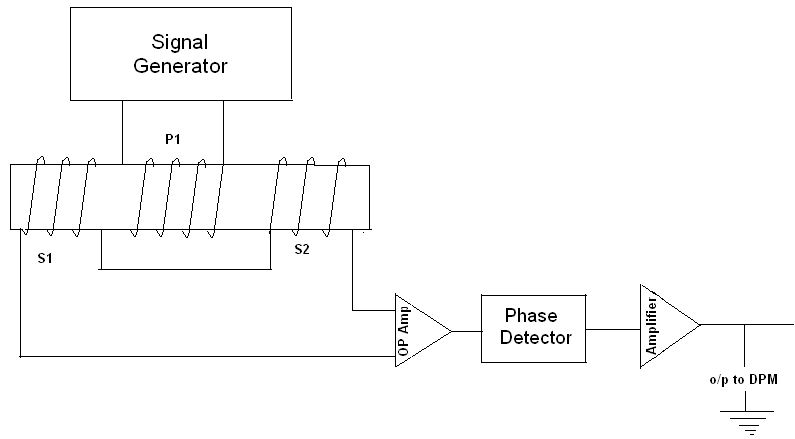

Schematic of LVDT setup | Download Scientific Diagram

NewTek Sensor Solutions Offers 4-20 mA Output on All LVDT Position...

Scheme of the LVDT sensor and principle of operation | Download

LVDT schematic drawing. (a) Four-wire LVDT. (b) Five-wire LVDT

Lvdt Schematic

Schematic diagram of the turbine test rig. LVDT: linear voltage

Learn About the Basics of LVDT Demodulator Circuits - Technical Articles

LVDT Electrical Schematic. | Download Scientific Diagram
